You are here:Home > Testing ServicesTesting per American Standards
Test per SAE J 844 for Nonmetallic Air Brake System Tubing

1. Scope
This SAE Standard covers the minimum requirements for nonmetallic tubing as manufactured for use in air brake systems. Non-reinforced products are designated type A and reinforced products, type B. It is not intended to cover tubing for any portion of the system which operates below –40 °C, above +93 °C, above a maximum working gage pressure of 1.0 MPa, or in an area subject to attack by battery acid. This tubing is intended for use in the brake system for connections, which maintain a basically fixed relationship between components during vehicle operation. Coiled tube assemblies required for those installations where flexing occurs are covered by this document, SAE J1131, and SAE J2494-3 to the extent of setting minimum requirements on the essentially straight tube and tube fitting connections which are used in the construction of such assemblies.
2. Dimensions and Tolerances
The tubing shall conform to dimensions shown in Table 1 under all conditions of moisture. Conformance with this requirement shall be determined on samples which have been subjected to 110 °C for 4 h in a circulating air oven, and on separate samples which have been immersed in boiling water for 2 h. Dimensional tests shall be made after samples have been returned to room temperature for 0.5 h to 3 h.
3. Performance Requirements
The tubing shall satisfactorily meet the following performance tests. Sections of these performance tests shall be conducted as Inspection Tests to be performed on each lot of tubing, and where a lot is defined as “the output of one production shift of one size and color of tubing.”
Inspection Tests are as follows:
Section 3.1 Leak Test
Section 3.9 Room Temperature Burst Test
Section 3.10 Cold Temperature Impact
Section 3.11 Adhesion
3.1 Leak Test
The tubing manufacturer shall subject each continuous length of tubing to test at a gage pressure of 1.4 MPa to 1.8 MPa with an appropriate gas for a period of time (minimum 30 s) sufficient to determine the presence of any leaks. Defective sections shall be cut off and scrapped. The remaining tubing shall be recoupled at the points where defective sections were removed and again subjected to the 1.4 MPa to 1.8 MPa pressure test. The procedure shall be repeated until all sections of tubing designated for distribution to users have successfully withstood the test.
3.2 Moisture Absorption
Expose sample of tubing for 24 h in a circulating air oven at 110 °C. Remove from oven, weigh immediately and expose for 100 h at 100% relative humidity and 24 °C. Within 5 min from humidity conditioning, wipe surface moisture from both the interior and exterior surfaces of the tubing and reweigh. Moisture absorption shall not exceed 2% by weight.
3.3 Ultraviolet Resistance
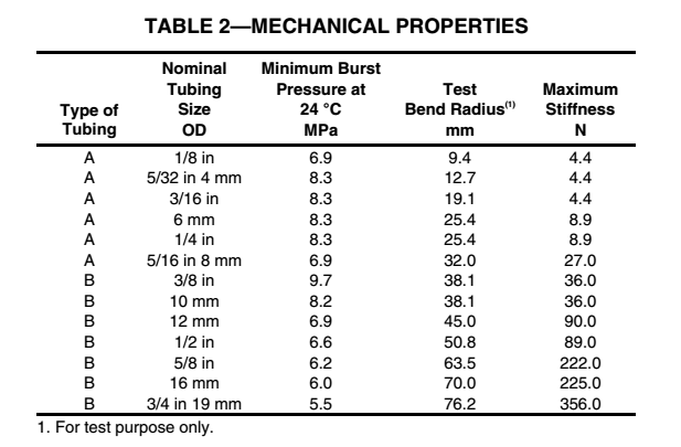
Place samples of tubing in the sample racks of a Q-Panel QUV test apparatus* equipped with Phillips bulbs, type UVA-340. Expose for 300 h minimum. If the test apparatus is equipped with a “Solar Eye,” the bulbs need not be rotated and the irradiance should be set at 0.85, however all bulbs should be discarded after 4800 h maximum, or if they fall below the 0.85 irradiance level, whichever occurs first. If the test apparatus is not equipped with a “Solar Eye,” the bulbs must be rotated every 400 h maximum, as recommended by the manufacturer and ASTM G 53, this procedure will result in discarding lamps after 1600 h of use. Control the temperature of the apparatus to 45 °C. The specimens are to be mounted on a plate such that the plate is no greater than 51 mm from the light bulbs. The automatic humidity cycling must be turned off. Rotate the specimens according to ASTM D 4329 except the time interval should be each 96 hours maximum instead of weekly. Maintain and operate the QUV tester in accordance with the manufacturers instructions. Immediately following this exposure, subject the tubing to the impact test shown in Figure 1. Subject tubing to room temperature burst as specified in 3.9. Tubing shall withstand no less than 80% of the burst pressure shown in Table 2.
|
|
|
|
 |
3.4 Temperature Flexibility
Expose sample of tubing for 24 h in a circulating air oven at 110 °C. Remove from oven and within 30 min expose for 4 h at –40 °C. Also expose a mandrel at –40 °C having a diameter equal to 12 times the nominal diameter of the tubing. (In order to obtain uniform temperatures, the tubing and mandrel may be supported by a nonmetallic surface during the entire period of test.) Immediately following this exposure, bend tubing 180 degrees over the mandrel, accomplishing the bending motion within a period of 4 to 8 s. The tubing shall show no evidence of fracture.
3.5 Heat Aging
Two separate heat aging tests shall be conducted; each phase shall be run on separate tubing samples. Subject tubing to room temperature burst test as specified in 3.9. Tubing shall withstand 80% of the burst pressure shown in Table 2.
3.5.1 Phase 1—Bend samples of tubing 180 degrees around a mandrel having a diameter equivalent to twice the test bend radius specified in Table 2. While in this position, expose tubing and mandrel for 72h in a circulating air oven at 110 °C. Remove from oven and permit tubing to return to 24 °C while still on the mandrel. Within 30 min after stabilization at 24 °C (75 °F), return the tubing to a straight position in a minimum of 4 s, then re-bend (against the set) 180 degrees around the mandrel, accomplishing the bending motion within a period of 4 to 8 s.
3.5.2 Phase 2—Expose samples of tubing for 72 h in a circulating air oven at 110 °C. Remove from oven and permit tubing to return to 24 °C. Within 30 min after stabilization at 24 °C, subject tubing to the impact test shown in Figure 1.
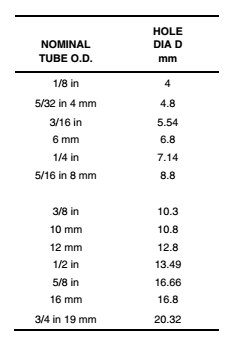
NOTE—Impact apparatus may be drilled to accept any combination of tube sizes listed in the chart
Impact apparatus falling mass shall be 0.454 kg, with a diameter of 31.75 mm, and a 15.88 mm spherical radius on each end. The mass falls 304.8 mm for 3/8" tubing.
Section A-A shows the typical hole location with respect to the impact area.
3.6 Resistance to Zinc Chloride
Bend tubing to the test bend radius shown in Table 2. While in this position, immerse in a 50% (by weight) aqueous solution of zinc chloride for 200 h at 24 °C. Remove from solution. Tubing shall show no evidence of cracking on the outside diameter.
NOTE—Fresh, anhydrous zinc chloride should be used to make up a concentration of 50% (by weight) aqueous solution (specific gravity of 1.576 or a Baume rating of 53 degrees at 16 °C).
3.7 Resistance to Methyl Alcohol
Bend tubing to the test bend radius shown in Table 2. While in this position, immerse in 95% methyl alcohol for 200 h at 24 °C. Remove from solution. Tubing shall show no evidence of cracking.
3.8 Stiffness
Use samples 280 mm long. Insert a rod of suitable size into the tubing to maintain a straight position within 3.2 mm. Expose tubing and rod for 24 h in a circulating air oven at 110 °C. Remove from oven and permit tubing and rod to return to 24 °C. Within 30 min after stabilization at 24 °C, remove rod and subject tubing to stiffness test shown in Figure 2. Tubing shall require no more force than specified in Table 2 to deflect 51 mm.
3.9 Room Temperature Burst Test
Tubing shall be stabilized for 0.5 to 3.0 h at 24 °C and tested by increasing pressure at a constant rate to reach the specified minimum burst pressure in Table 2 within a time period of 3 to 15 s. Tubing that bursts below the pressure specified in Table 2 shall be rejected.
3.10 Cold Temperature Impact
Condition tubing by exposing one half the samples for 24 h at 110 °C in a circulating air oven, and one half the samples in boiling water for 2 h; then expose all the samples to –40 °C for 4 h. Also, expose impact test apparatus, shown in Figure 1, to –40 °C. While tubing and apparatus are at this cold temperature (approximately –40 °C), subject tubing to impact as specified. The tubing shall show no evidence of cracks. After impact testing, permit tubing to return to 24 °C. Within 30 min after stabilization at 24 °C, subject tubing to room temperature burst test as specified in 3.10. Tubing shall withstand at least 80% of the burst pressure shown in Table 2. Sample size shall be 10 specimens per lot. In the event of any failures, a second sample from the same lot consisting of 20 specimens shall be tested. If another failure occurs, the lot shall be rejected.
3.11 Adhesion Test
3.11.1 This test applies only to the reinforced products, Type B.
3.11.2 CONDITION
This test shall be conducted at 24 °C ambient temperature.
3.11.3 PROCEDURE AND REQUIREMENTS
Cut a strip of tubing into a 6.0 mm wide helical coil equal in length to five times the circumference of the tubing. Bend the helical coil in reverse of coiling so as to expose the braid gap between the outer jacket and core tube section. Start by working a sharp knife blade into the braid gap to initiate separation, and then attempt to separate the outer jacket from the core tube at the braid interstices. The bonded surface (excluding the braided area) between the outer jacket and core section shall be inseparable for the entire test sample length.
3.12 Heat Aging Adhesion Test
3.12.1PROCEDURE
Subject samples to Phase 1 of the heat aging test procedure per 3.5.1.
3.12.1 REQUIREMENTS
After completion of the Phase 1 procedure, the tubing shall meet the requirements of 3.11.
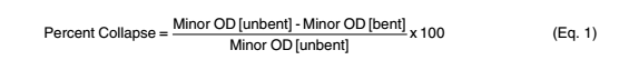
3.13 Collapse Resistance Test Procedure
3.13.1 GENERAL
All tests are to be conducted at room temperature 24 °C unless otherwise specified.
3.13.2 PREPARATION OF TEST SAMPLES
3.13.2 PREPARATION OF TEST SAMPLES
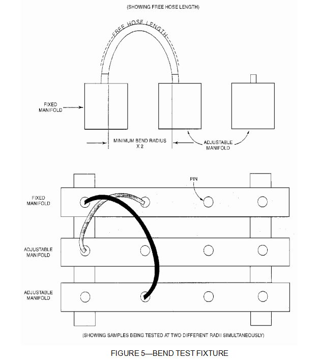
Three samples shall be prepared for testing. The free tube length of the samples shall be as follows:
3.14 x (min kink radius) + 10 x (tube OD) + 2 x (length of supporting pin)
3.13.3 TEST PROCEDURE
Place a reference mark at the middle of each sample and measure the cross section diameter (Minor Diameter [unbent]) at this point and record.
NOTE—See Figures 3 and 4 for location of minor diameters.
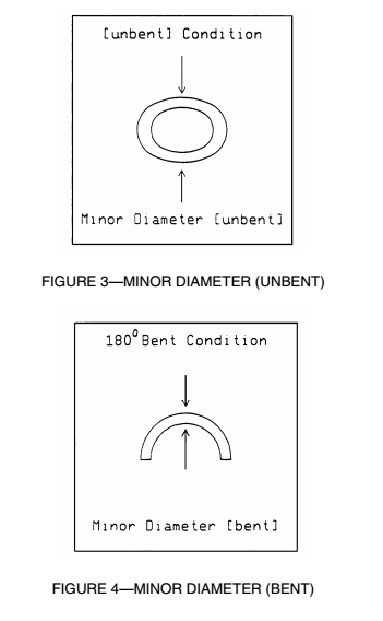
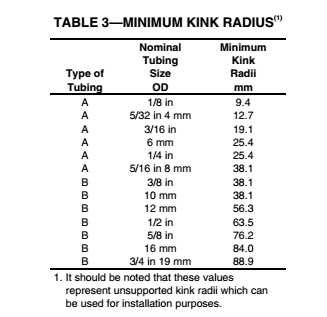
3.13.4 Carefully install the samples on a bend test fixture (as shown in Figure 5) in a 180-degree bend condition. The tube shall be bent in the direction of the natural curvature of the tube. Samples prepared per 3.13.2 shall be bent to a radius equal to the minimum kink radius called out in Table 3.
|
|
|
|
3.13.5 Age samples on test fixture at 93 °C for 24 h. Allow the samples to cool to room temperature. While the samples are on the test fixture, measure the minor diameter (bent). Collapse of greater than 20% is considered a failure (see Equation 1). |