You are here:Home > Testing ServicesTesting per American Standards
Test per SAE J 1402 for Automotive Air Brake Hose and Hose Assemblies
1. SCOPE
This recommended practice covers minimum requirements for air brake hose assemblies made from reinforced elastomeric hose and suitable fittings for use in automotive air brake systems including flexible connections from frame to axle, tractor to trailer, trailer to trailer and other unshielded air lines with air pressures up to 1 MPa, that are exposed to potential pull or impact. This hose is not to be used where temperatures, external or internal, fall outside the range of-40 °C to +100 °C.
2. HOSE CONSTRUCTIONS AND DIMENSIONS
There are four distinct hose constructions used for air brake hose assemblies made from reinforced elastomeric hose. All dimensions are in accordance with Tables1 and 2.
Type A consists of an elastomeric tube, a fiber reinforcement and an elastomeric cover.
Type AI consists of an elastomeric tube, a wire or fiber reinforcement and a fiber braid cover.
Type AII consists of an elastomeric tube, a wire or fiber reinforcement and a fiber braid or elastomeric cover. This hose is dimensionally identical to SAE J517 100R5 hose.
Type AIII consists of an elastomeric tube, wire or fiber reinforcement and a firber braid or elastomeric cover.
.png)
NOTE: The sizes 3/8, 7/16 and 1/2 SP of Type A hose can be assembled with field attachable fittings if desired. These field attachable fittings are not the same as used with Types AI and AII hoses. AIII hoses are assembled with permanent crimp fittings only.
.png)
3. MINIMUM BEND RADIUS
.png)
4. PERFORMANCE
NOTE 1: All samples subjected to one or more performance tests other than Proof Pressure and Length Change shall be destroyed and discarded after completion of the tests and their analysis.
NOTE 2: Burst Strength and Assembly Tensile Strength tests are qualification tests and do not imply that the hose assemblies can be used under those conditions.
4.1 Acceptance Performance
Hose or hose assemblies at the time of manufacture shall conform to the following:
4.1.1 End Fittings
End fittings shall be such as to permit conformance to all portions of this recommended practice. After assembly of the end fittings to the hose, the minimum I.D. of the end fittings or the hose shall not be less than 66% of the minimum hose ID shown in Table 1. All hose assemblies shall pass this requirement prior to conducting any other test in this recommended practice.
4.1.2 Proof Pressure
Assemblies subjected to a pressure test using 2 MPa ± 0.1 MPa air or nitrogen under water for a minimum of 30 s shall show no leaks.
4.1.3 Burst Strength
There shall be no hose burst, leakage or end fitting separation below 6 MPa when hose or hose assemblies are subjected to a hydrostatic burst test using water.
4.1.4 Assembly Tensile Strength
450 mm long hose assemblies including the fittings shall be subjected to a longitudinal tensile test at a steady rate of 25 mm/min ± 2.5 mm/min until separation of the hose from the fittings or rupture of the hose occurs. Failure of the 6.3 mm and smaller size shall occur at no less than 1100 N and larger sizes at no less than 1450 N.
4.1.5 Length Change
Test for length change shall be conducted in accordance with ASTM D 380 (Elongation and Contraction) with the original measurement made at 0.1 MPa. The change in length shall be determined at 1.5 MPa and shall be from +5% to –7%.
4.1.6 Adhesion
Tests for adhesion shall be conducted only on original unaged specimens as follows:
4.1.6.1 Adhesion of Fiber Reinforced Hose
Test for adhesion shall be conducted in accordance with ASTM D 413 Machine Method, and the average load
required to separate any adjacent layers shall be 1.4 N/mm minimum.
Type AIII consists of an elastomeric tube, wire or fiber reinforcement and a fiber braid or elastomeric cover.
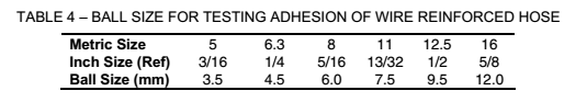
4.1.6.2 Adhesion of Wire Reinforced Hose
The requirements and method of testing cover adhesion for Type AI, AII and AIII hoses with wire reinforcement shall be as in 4.1.6.1. The integrity of the inner tube adhesion shall be tested by subjecting a length of hose not less than 380 mm long to the following requirements:
Place a steel ball of the size specified in Table 4 in the bore of the hose. One end of the hose shall be attached to a vacuum source and the other end plugged. A vacuum of 17 kPa absolute shall be applied for a period of 5 min while the hose is in an essentially straight position. At the conclusion of this period and while still under vacuum, the hose shall be bent 180° to the minimum bend radius in Table 3 in each of two directions 180° apart. After bending and returning to an essentially straight position and while still under vacuum, the ball shall be rolled from end to end of the hose. Failure of the ball to pass freely from end to end shall be indication of separation of the inner tube from the reinforcement layer and shall constitute failure.
|
|
|
|
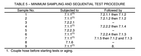
4.2 Qualification Performance |
For initial qualification under this specification all of the requirements under Acceptance Performance, Qualification Performance and Flexure Test shall be met. Minimum sampling shall be per Table 5, including the specified sequential test procedure.
|
|
|
|
4.2.1 Temperature Resistance |
4.2.1.1 High Temperature Resistance
The hose portion of a hose assembly shall show no cracks, charring or disintegration externally or internally when straightened after being bent over a form for a period of 70 h ± 2 h while in an air oven at 100 °C ± 2 °C. The radius of the test form shall be in accordance with Table 3. The external surface of fiber braid covered hoses shall be exempt from inspection for cracks as visual inspection is not practical.
After completion of this test, the hose assembly shall be tested in accordance with 4.1.2 Proof Pressure.
4.2.1.2 Low Temperature Resistance
The hose shall show no cracks externally or internally when bent 180° over a form having the radius shown in Table 3 after hose and form have been exposed for a period of 70 h ± 2 h in an air circulating chamber at –40 °C ± 2 °C and while still at this temperature. The hose and form shall be supported by a non-metallic surface during the entire period. The bend shall be completed in a period of 3 s to 5 s. The external surface of fiber braid covered hoses shall be exempt from inspection for cracks as visual inspection is not practical.
4.2.2 Resistance to Environment
4.2.2.1 Oil
Specimens prepared from the inner tube and the cover shall show a volume increase when measured after removal from ASTM IRM 903 oil in which it has been immersed for 70 h ± 2 h at 100 °C ± 2 °C of not more than 100%.
4.2.2.2 Water
Condition hose assembly by immersion in distilled water at room temperature for a period of 168 h ± 2 h while bent over a form having the minimum bend radius shown in Table 3. Ends shall be completely capped during immersion.
After completion of this test, the hose assembly shall be tested in accordance with 4.1.4 Assembly Tensile Strength.
4.2.2.3 Ozone
After being exposed for 70 h ± 2 h in an ozone test cabinet with an atmosphere comprised of air and ozone with an ozone partial pressure of 100 mPa (100 parts of ozone per 100 million parts of air) at standard atmospheric conditions at an ambient temperature of 40 °C ± 2 °C and while bent over a form having the radius shown in Table 3, the hose shall show no cracking under 7X magnification. This test only applies to elastomeric covered hoses.
4.2.2.4 Salt Spray Test
A hose assembly, while supported or suspended between 15 and 30 degrees from vertical, shall withstand 24 h ± 1 h exposure to salt spray when tested in accordance with ASTM B 117, Method of Salt Spray (Fog) Testing. After this exposure, fittings shall show no base metal corrosion except red rust is acceptable in areas of identification stamping and crimp distortions. White corrosion products are acceptable.
After completion of this test, the hose assembly shall be tested in accordance with 4.1.3 Burst Strength.
5. FLEXURE TEST
5.1 Preparation of Test Samples
|
|
|
|
5.1.1 Prior to cutting the hose, apply a layline (of a color distinguishable from that of the hose cover) along the length of the hose (following the natural hose curvature which results from the hose being coiled in a roll) as shown in Figure 1. |
.png)
5.1.2 Cut the hose to provide a hose assembly sample with a free hose length as shown in Figure 2 and Table 6. Free hose length is the outside exposed hose length between the fittings in the finished hose assembly.
5.1.3 Fittings are to be assembled on the hose in accordance with the manufacturer’s instructions.
5.2 Preconditioning
Subject each sample hose assembly to the salt spray conditioning specified in 5.2.1, followed by the high temperature aging specified in 5.2.2.
5.2.1 Salt Spray Conditioning
With the ends plugged, subject the hose assembly samples to 24 h ± 1 h exposure to salt spray testing in accordance with ASTM B 117, Method of Salt Spray (Fog) Testing.
Allow no more than 168 h elapsed time between completion of the salt spray conditioning and the start of the high temperature aging per 5.2.2.
5.2.2 High Temperature Aging
5.3 Installation of Samples in the Test Setup
|
|
|
|
After the samples have been preconditioned, they are to be installed in the test setup in the configuration specified in Figure 2 and Table 6. The installation procedure is as follows: |
.png)
5.3.1 With the movable manifold of the flex test machine at the center of its stroke, fitting “B” is connected to the movable manifold in such a manner that the layline is located at the top-center position (See Figure 2).
5.3.2 After fitting “B” has been coupled with the movable manifold, the “A” fitting is then connected to the stationary manifold without imparting any twist to the hose, but allowing the hose to seek its natural curvature.
5.4 Test Procedure
5.4.1.1 Flexure/Pressure Cycling Test Parameters
150 mm ± 1.5 mm.
5.4.1.2 Total Flexure Stroke
1.7 Hz ± 0.1 Hz
5.4.1.3 Ambient Temperature
26 °C ± 6 °C.
5.4.1.4 Internal Air Pressure on Test Samples
1 MPa ± 0.1 MPa.
The air pressure shall be alternately fully “on” for 60 s ± 5 s and fully “off” for 60 s ± 5 s
5.5 Termination of Flexure Test
The failure point (number of flex stroke cycles) shall be determined by loss of air pressure through the failed sample. As the air pressure is alternately fully “on” for 60 s and fully “off” for 60 s, pressure loss shall be further described as failure of the system to be repressurized to 1 MPa ± 0.1 MPa through a 1.6 mm +0.05 –0.00 mm diameter orifice within 2 min. Failure shall not occur before completing one million flex cycles.